VRV/VRF installation technology has shown to be extremely dependable when used and installed correctly. When the quality of the installation isn’t a priority and the manufacturer’s installation manuals aren’t followed correctly, problems arise.
We recommend considering the following guidelines for project success in order to avoid problems during the installation and/or operation of the VRV/VRF system for building owners or managers with no prior experience with VRV/VRF units.
What steps are included in a typical installation workflow of VRV/VRF?
- Mounting indoor unit/fan coil
- Assemble and connect refrigeration piping
- Installing Y branch copper fittings also known as refnets or/and branch boxes for heat recovery systems
- Providing drainage
- Connecting communication and electrical wiring and install controllers
- Checking the refrigerant piping
- Installing outdoor unit
- Charging refrigerant
- Commissioning and testing the system
Refrigeration pipework
During brazing, oxidation in refrigerant pipes can cause blocked strainers, restricted flow through EEVs, and other problems in the system. Refrigerant piping should have brazing with a dry nitrogen purge to prevent oxidation during installation.
DO NOT USE FLUX when brazing copper-to-copper refrigerant piping. Flux has a devastating effect on refrigerant pipe systems. For example, adding a chlorine-based flux can cause pipe corrosion, while adding fluorine will deteriorate the refrigerant oil.
Torque all flared connections to standard torque values corresponding to flare nut size.
For refrigerant branching or refnet installation, mount the refnet joint so that it branches horizontally or vertically.
Connecting the refrigerant piping.
When connecting pipes, keep the following in mind:
- While loosening the flare nut, always use two wrenches simultaneously.
- When joining the pipework, always use a spanner and torque wrench jointly to tighten the flare nut. This is to avoid nut cracking and leakage.
- Use vacuum pump oil to lubricate the flare inner surface when attaching a flare nut. Twist flare nut by hand before fastening firmly.
Pipe insulation requirements
All piping insulation should meet the manufacturer’s minimum thickness requirements as well as the National Construction Code (NCC 2019). Capacity reduction, efficiency, and condensation formation are some of the adverse effects of an inadequate insulation system.
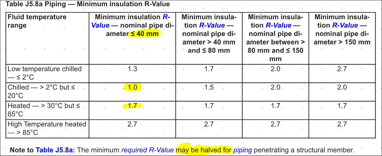
Thermal resistance, often known as R-Value, is a measurement of a material’s ability to resist heat flow.
Thermal resistance values are expressed using a combination of numbers and thermal resistance: Resistance units are represented by R-2. The better the insulation, the greater the R-value.
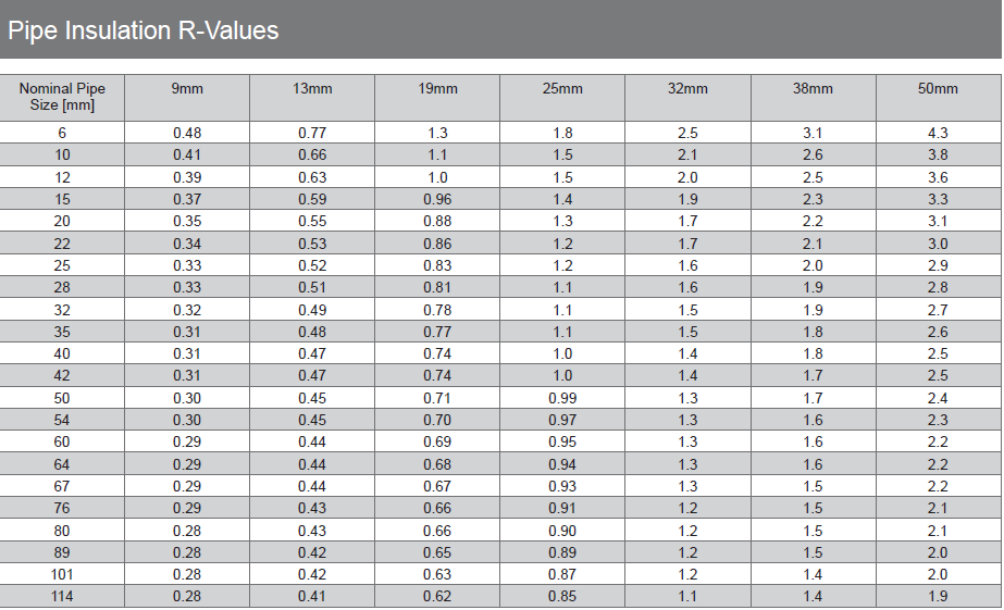
The Material R-Values for Armaflex pipe insulation are listed in the table below, and values are determined in compliance with AS/NZS 4589.1 (clause 2.3.3.8).
Typical R-values for Armaflex FRV insulation
Leak testing
If moisture is suspected to be present in the refrigerant piping (for example, water may have entered the piping), do the vacuum drying technique outlined below until all moisture is eliminated.
All pipes inside the machine should have a leak-test at the factory.
Only the field-install refrigerant piping must have a pre-inspection.
As a result, before performing a leak test or vacuum drying, ensure that all outdoor unit stop valves are securely closed.
Vacuum leak test.
Pressure testing ensures a leak-free system, which is essential for a successful installation.
- For more than 2 hours, evacuate the system from the liquid and gas pipelines to –500 microns.
- When the target reaches 500 microns, turn off the vacuum pump and wait at least 1 minute to see if the pressure rises.
- The system may contain moisture or have leaks if the pressure rises.
Pressure leak test.
- Break the vacuum by applying a minimum gauge pressure of 0.2 MPa with nitrogen gas (2 bar). Never set the gauge pressure higher than the unit’s maximum operating pressure, which is 4.0 MPa (40 bar).
- Apply a bubble test solution to all piping connections to check for leaks.
- Remove all nitrogen gas.

Refrigerant charging
The outdoor unit is pre-charged with refrigerant, but you may need to charge additional refrigerant depending on the field pipework.
The following steps usually follow when adding more refrigerant:
1 Calculating how much you’ll have to charge extra.
2 Adding more refrigerant to the system (pre-charging and/or charging).
3 Complete the fluorinated greenhouse gases label and stick it to the inside of the outdoor unit.

Communication and power wiring
It is critical to keep the power supply and the transmission cables separate. To avoid electrical interference, the distance between the two cables should always be at least 50 mm.
- ONLY use copper wires.
- Make sure you have earth wire in place. The item should not be earth to a utility pipe, surge absorber, or phone ground. Incomplete earth can cause electrical shock.
- Ensure that a dedicated power circuit is being used. NEVER use another device’s power supply.
- Ensure that an earth leakage protector installation is proper. If not, electrical shock or fire can occur.
- A certified electrician should install all the wiring and components, and adhere to all applicable laws.
- Transmission wire must be at least 75-1.25mm2 sheath shield (2-core wire)